
In last month’s column, we discussed the design and actuation of 3-way diverter valves. This month, we’ll look at several applications for these valves.
Keeping It moving
The “classic” method of zoning a hydronic system is to start and stop flow through a zone circuit based on calls from a room thermostat. Flow control could be based on turning a zone circulator on and off, or operating an on/off zone valve.
Although this strategy has certainly worked in hundreds of thousands of systems, there are situations where it’s not ideal. One is zoning a slab-on-grade floor heating system in a commercial building with large overhead doors.
During very cold weather, water in the embedded tubing closest to the overhead doors can freeze if the thermostat controlling the zone turns off flow for several hours. This can occur if the zone thermostat is turned down several degrees for any reason (night setback, weekend setback, worker “prank,” owner frustrated with fuel cost, etc.) Believe me, it happens…
This condition makes the slab just inside an overhead door “thermally vulnerable” due to infiltration of cold outside air under the door seal, as well as conduction heat loss through the slab. The latter is of particular concern when there’s no thermal break in the slab under the door. Figure 1 illustrates the situation.
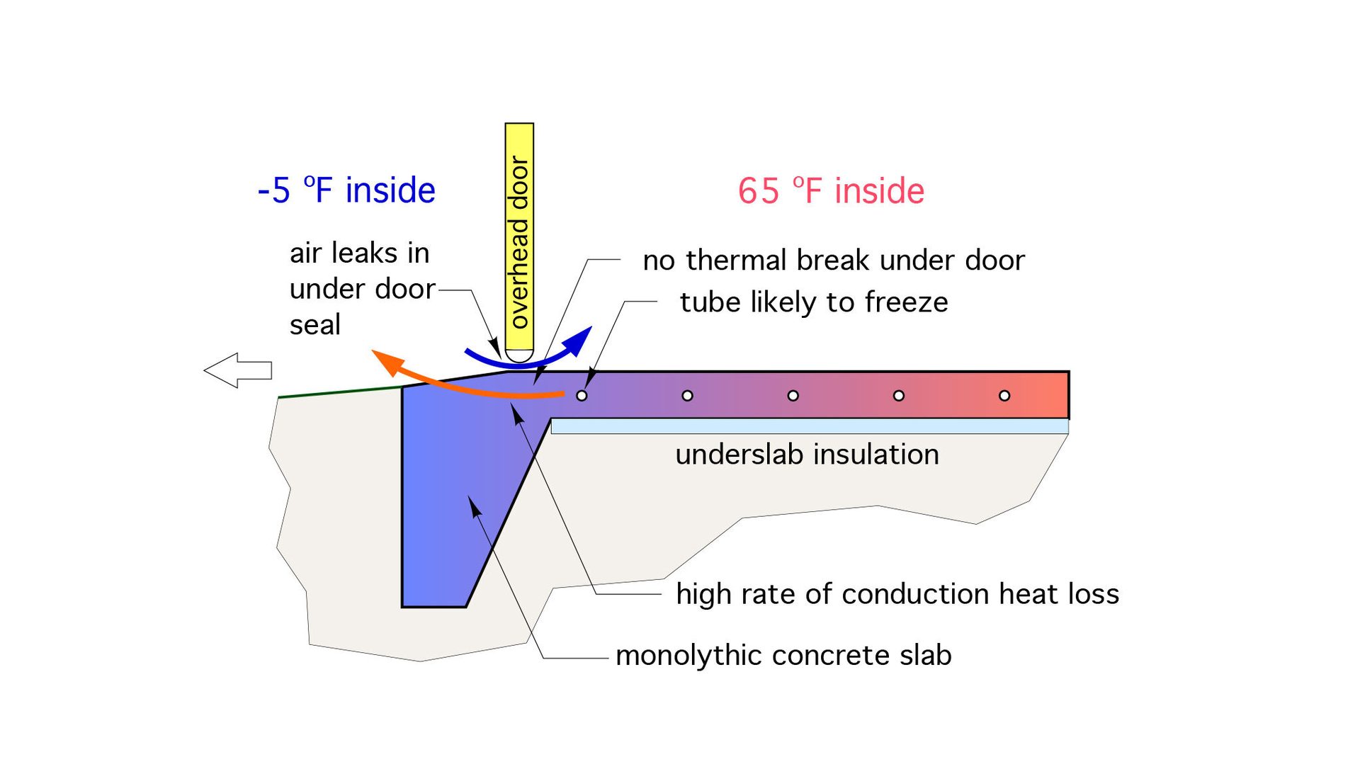
Figure 1
One way to prevent a potential freeze is to use an antifreeze solution in the system. However, that can get expensive in systems that may have several hundred gallons of total volume, in tubing, manifold supply piping, headers, buffer tanks, boilers, etc.
In addition to added cost, antifreeze also brings along undesirable traits such as higher viscosity, lower specific heat, pH maintenance and a propensity to leak through threaded joints that are not perfectly executed.
An alternative is to operate the system with water, but keep that water moving through the floor heating circuits, even when no heat needs to be added to the zone.
In a multi-zone system, this can be done by using 3-way diverter valves as shown in Figure 2.
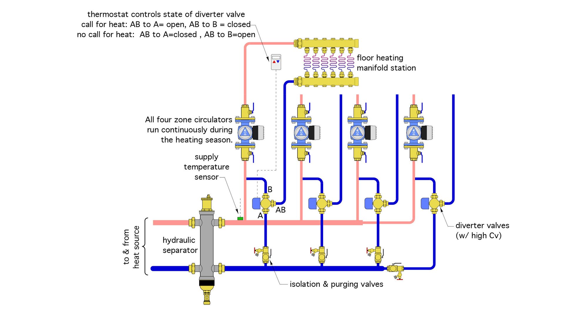
Figure 2
The circulator in each zone operates continuously during the heating season. Each zone thermostat determines the status of its associated diverter valve. When a zone thermostat calls for heat, the path from its inlet port (AB) to outlet port (A) is open. This allows flow returning from the manifold station to flow to the return header and back through the hydraulic separator to the heat source. An equal flow rate of heated water flows from the header to the supply manifold. In this state, the path from the inlet port (AB) to port (B) is closed, and thus none of the flow returning from the manifold station can go back to the supply side of the system.
When a zone thermostat is satisfied, the actuator operating the diverter valve moves the internal ball so that the path from inlet port (AB) to port (B) is open and the path from (AB to A) is closed. This allows recirculation of flow returning from the manifold station without adding heat.
Each zone operates the same way, and completely independent of the other zones.
Outdoor reset of the supply water temperature is preferred to minimize any overshoot or undershoot in space temperature.
Heat pump applications
Air-to-water heat pumps and geothermal water-to-water heat pumps are quickly gaining market share as heating (and cooling) sources for hydronic systems. Both can produce heated water or chilled water. When the system operates in chilled water cooling mode the water stream leaving the heat pump is usually routed to a different subsystem from that used for heating. Diversion valves make this easy.
Figure 3 shows a system where chilled water is routed to an air handler for cooling mode, and to a buffer tank when the system operates in heating mode.
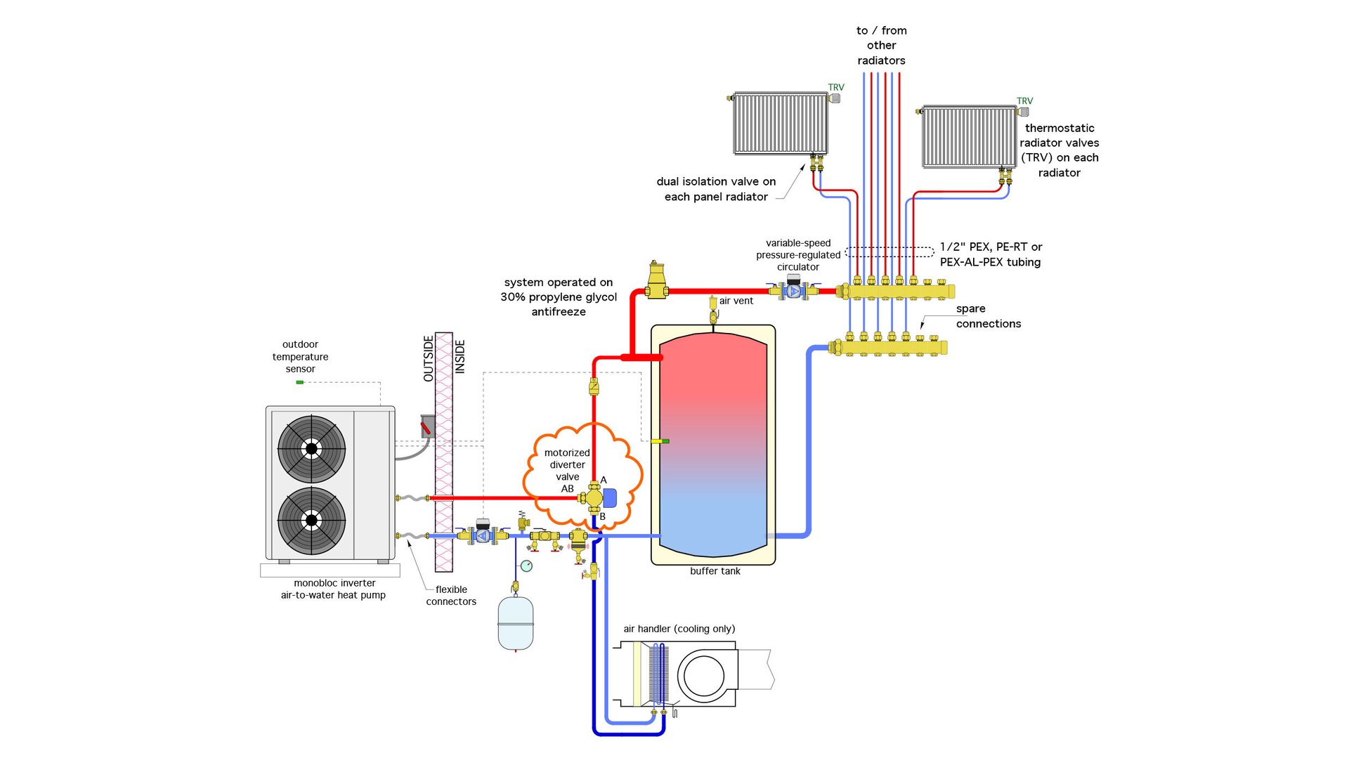
Figure 3
Sticking with heat pump systems, some have three loads; space heating, cooling and domestic water heating. In this case, a second diverter valve can be used to direct heated water leaving the heat pump to the space heating portion of the system or through the coil of an indirect water heating tank, as shown in Figure 4.
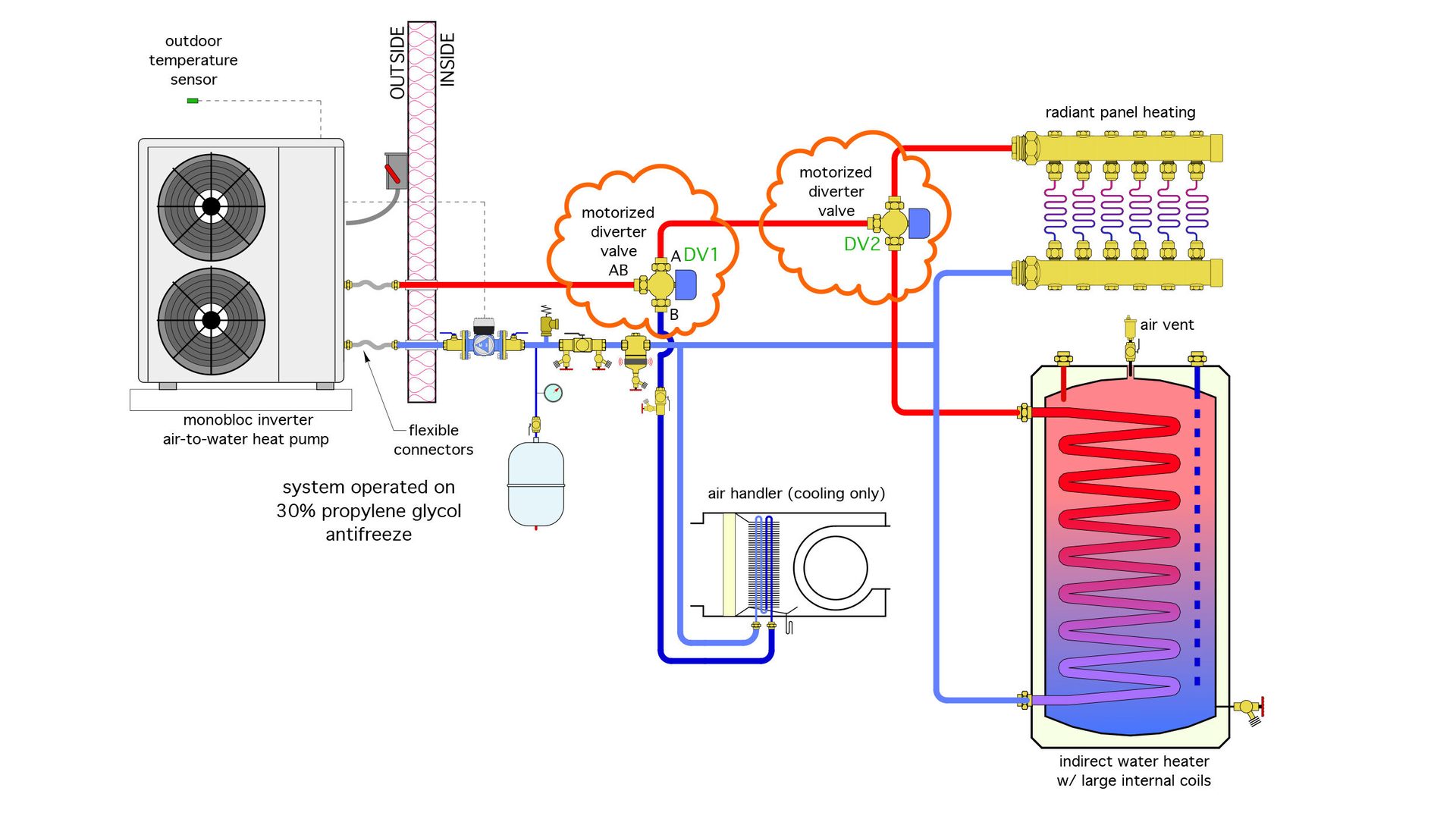
Figure 4
Multiple heat pump systems
There are applications where multiple hydronic heat pumps are connected to a 4-pipe header system. Any of the heat pumps can be called to operate in heating or cooling, depending on current loads.
This is another application where a 3-way diverter valve combined with two on/off motorized valves can be used to connect the heat pump to the appropriate supply and return headers and prevent flow through the heat pump when it’s off. Figure 5 shows an example using 3 independently controlled air-to-water heat pumps.
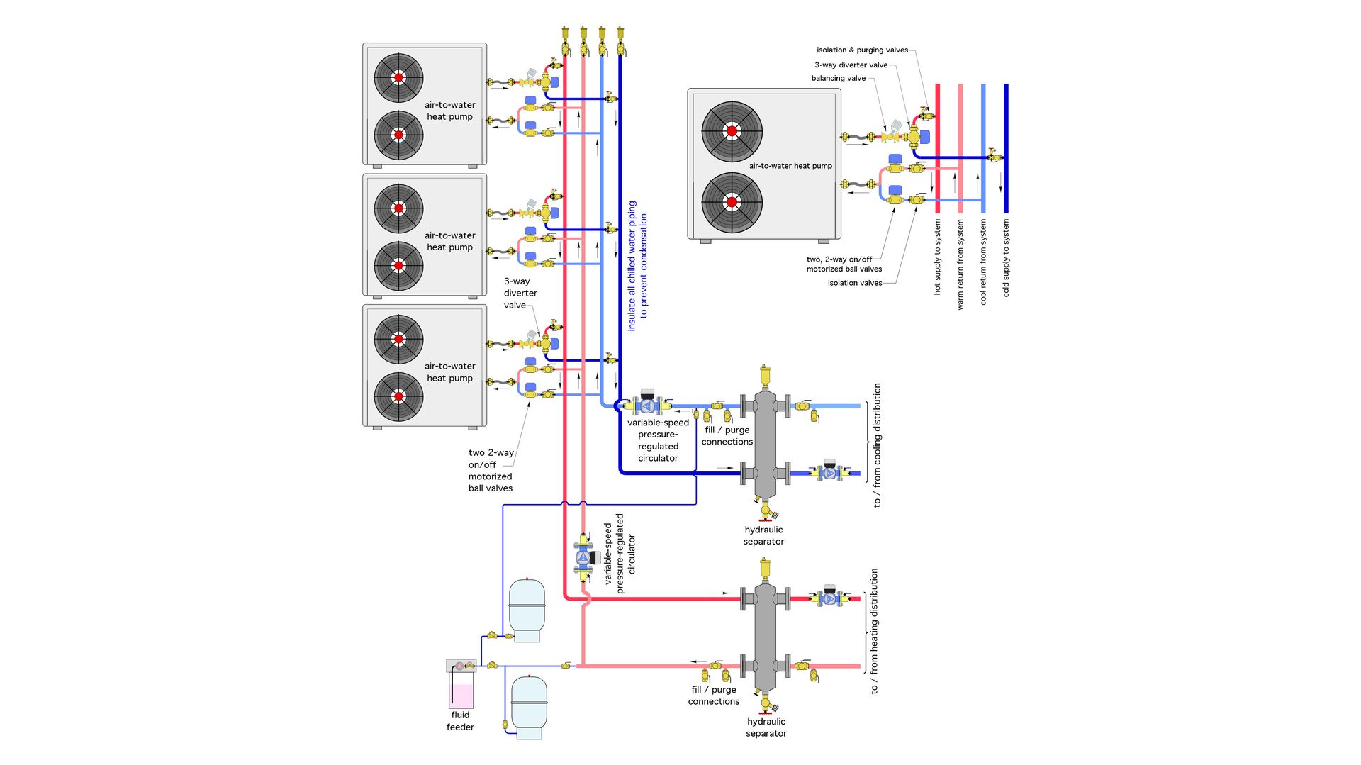
Figure 5
You might be wondering; why not just use two 3-way diverter valves on each heat pump? The problem is that standard 3-way diverter valves cannot block flow from the cooling headers or heating headers from passing through the heat pump when it is off. This flow blocking is necessary to prevent “thermally diluting” the heating or cooling headers. Preventing flow through inactive heat pumps also reduces pumping power. Both two 2-ways valves shown to the left of each heat pump in Figure 5 would be closed when their associated heat pump is off.
One more twist
The two 2-way motorized valves on each heat pump in Figure 5 could be replaced by a single 3-way/3-position diverting valve. Such a valve would have a third position for its internal ball that would block flow through the valve's common port. Figure 6 shows the concept.
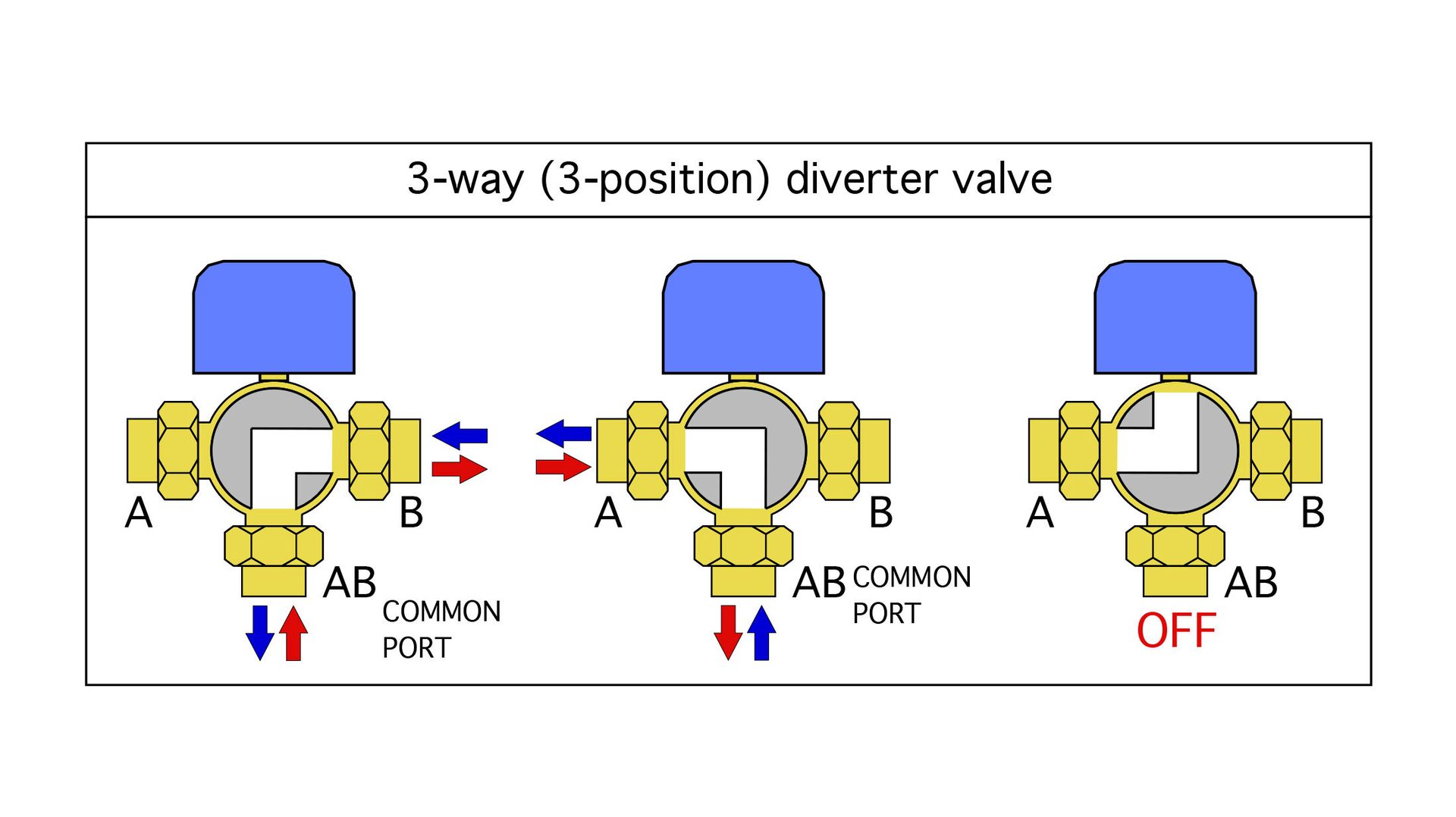
Figure 6
Figure 7 shows how a 3-way, 3-position diverter valve would be used in a multiple air-to-water heat pump system, where the ability to connect each heat pump to either the heating headers or cooling headers is required, as well as preventing flow through the heat pump when it’s off.

Figure 7
Notice that only one of the two 3-way diverter valves is a 3-position valve. The other 3-way valve has a “T” pattern ball that doesn’t block flow through the heat pump in either of its two operating positions. This allows the heat pump and nearby piping to remain “in communication” with one of the system’s expansion tanks when it’s not operating. Doing so prevents wide pressure changes in the heat pump and nearby piping due to changing fluid temperatures in what would otherwise be a portion of the system that’s completely isolated from the expansion tank. A 2-position, 3-way diverter valve with an “L” pattern drilling could also be used in lieu of the valve with the “T” pattern drilling.
The same piping and valves shown in Figure 7 could be used to connect multiple 2-pipe air handler coils to a 4-pipe distribution system.
At this time I’m not aware of any current supplier of 3-way / 3-position diverter valves in the North American market.
Opportunity awaits.
If someone reading this knows of a supplier please let me know.
Forks in the road
Three-way diverter valves have several potential applications in modern hydronic heating and cooling systems. They’re available in a wide range of pipe sizes, and actuator options. Some are also available with form-fitting insulation shells for chilled water cooling applications. Be sure to keep them in your design toolkit.


